Introducing the Bumble-b and using it to control a LED matrix October 8, 2009
Posted by GuySoft in Crictor, diy, Electronics, Hamakor, ITU, open source, programming.Tags: bumble-b, diy, Electronics, howto, leds, linux, open source, programming, usb
trackback

The Bumble-b
Hi all,
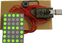
The past week I have been playing around with my new Bumble-b, as I mentioned in my last post. Basically what I did with it is control an LED matrix. After doing that I made it in to a USB Device! Thanks to the simple library LUFA. Now I can use a simple echo > /dev/ttyACM0 command to send a text message to the display. Meaning that I have now /dev/matrix!
In this post I hope to explain how to use the Bumble-b, a programmable USB chip, including its own built in programmer, for just $20. I would also like to encourage people here in Israel to start playing with this, since its cheap and easy to order way to get started with amateur electronics.
Here is a quick introduction video (followed by a detail post):
 What is the Bumble-b?
The bumble-b is a USB programmable AVR chip with a programmer built in to it (called a breakout board). It is an AVR chip, meaning that its based on something that is widely used (the model is at90usb162). Moreover, since it has a USB connector right on it , this makes the creation of USB devices really simple. But not only USB devices alone.
For those who are thinking about getting an arduino, the main advantage I can see to an arduino over the Bumble-b is that it has analog-to-digital converters, which means its more built for connecting sensors, for things like robots. If that is not what you’re looking for, the Bumble-b will serve you well as a starting project, and is cheaper.
For more information, check out dflecher’s website (also for ordering), the bumble-b datasheet and the #bumbleb IRC channel.
Compiling code with gcc-avr (yes! now with 100% gcc)
Although I am linking here to a scripts I wrote, which should help you avoid writing in the shell, I do want to stress, that unlike the PIC project, here the compiler that is used is gcc-avr, which is fully open source. I will get in to the specifics of how to use it in the IDE section.
How to get it in to programming mode
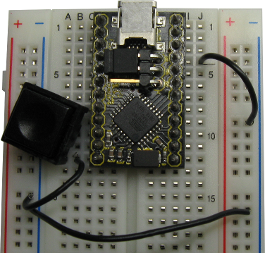
If you get a Bumble-b and plug it in right away, it will identify itself as a serial device on your computer. This is NOT the programmer, this is an initial program dflecher ships the Bumble-b with. The program lets you control the pins by sending them serial calls. Although it really is a useful program, you will want to install your own. To do that you need to set the Bumble-b to DFU mode (Device Firmware Update). This is mentioned in the schematic, but I will go over it here again:
- Connect pin 21 (HWB) to pin 12 (GND)
- connect a button between pin 9 (RESET) and pin 12 (GND)

Bumble-b in programmer mode
Now to go in to DFU mode press the REST button you installed. You should see in dmesg output:
usb 3-2: new full speed USB device using uhci_hcd and address 13

usb 3-2: New USB device found, idVendor=03eb, idProduct=2ffa

usb 3-2: New USB device strings: Mfr=1, Product=2, SerialNumber=3

usb 3-2: Product: AT90USB162 DFU

usb 3-2: Manufacturer: ATMEL

usb 3-2: SerialNumber: 1.0.5
After getting in to programming mode, you can upload compiled .hex files to it. The programmer that is used is called dfu-programmer. It exists in the Debian repository (Kaplan, no excuses now). The commands to flash a .hex file will be:
dfu-programmer  at90usb162 erase

dfu-programmer  at90usb162 flash program.hex
But you can just use the scripts I wrote to do this. As explained in the next section.
Setting up an IDE environment in linux
The frustrating part for me was that unlike piklab that I used for the PICs, I could not find an IDE that will support the Bumble-b’s dfu-programmer out of the box. But rest assured! I found how to set one up. Thanks to Ori Iran’s guidelines I manage to set up an lightweight IDE called Geany to work with the bumble-b. Here are the steps:
- Download my script packages. And extract them where you want to develop.
- Get Geany with your distro’s repository, and open it.
- Create a new .c file and save it (you can also open “hello_world.c” in the script package).
- Open the ‘Build’ menu and select “Set includes and arguments”, You should get the window in the photo.
- Set the fields as shown in the photo below (“./compile %f” in compile field, “./program %f” in the build field, and “./run” in the execute field”).
- You are good to go. Now to program just press ‘compile’, then “build” and ‘execute’ (don’t forget to press the RESET button before pressing ‘build’!).


The Geany IDE
LUFA library – How easy it is to make USB devices
After getting my LED matrix to display messages, I wanted to make use of the USB port, and get the matrix to work as a USB device, this was much simpler than I expected. Once I had the code to control the matrix, it was simply a matter of copying it and using LUFA.
LUFA (Lightweight USB Framework for AVRs) is a library that will let you get the Bumble-b to work as a USB device. It can be used as a mouse, a keyboard, a joystick, a storage device and anything really (there is a full list is on the site).
To get the LED matrix to work off USB, all I had to do is copy the Demo that located in Demos/Device/ClassDriver/CDC. I also used code modified by dflecher (he built a USB missile launcher with it). Note that you will change the following lines in the makefiles of the LUFA Demo in order to use it with the bumble-b:
- BOARD=BUMBLEB
- MCU=at90usb162
- F_CPU = 16000000
There is more info about what pins do (like joysticks buttons) in the LUFA readme on the bumble-b.
You can also download my matrix code and have a look.
More info?
- I will mention again that there is an IRC chat room for the #bumbleb on freenode. There is also a chat room on AVRs in general.
- dflecher’s site has all the information about the bumble-b. Also a great thanks to him for putting up with my questions 🙂 .
- AVR freaks is also a good place to look for things.
- You can also take a look at the youtube videos I have been posting the last few days
Code published in the post
Just to make sure you saw all the code published in the post
- Geany-Bumble-b scripts
- matrix.c code without the USB control
- Matrix control with the LUFA library (type ‘make’ in the CDC_matrix dir to compile).
That’s it. What are you waiting for? Amateur electronics is at your grasp!
[…] shows us how to create a Bumble-b LED Matrix Computer Interface. I have never used a Bumble-b but for $17 how could you go wrong? It seams like one of the best […]
wow.. i want to learn how to make it.. real cool man.. =)
can you post the circuit diagram? or at least how you make the conections from the matrix to the bumble-b
Well, I am afraid I don’t have one. Also its not really relevant because each matrix is different.
I really just plugged pin1 to portB0, and so on, until I ran out of pins, then used port D.
I wrote the pin connections in a comment in this code
/* Pin connection layout for the SUN MUG50A matrix and the bumble-b

1	B0

2	B1

3	B2

4	B3

5	B4

6	B5

7	B6

8	D0

9	D1

10	D2

11	D3

12	D4

13	D5

14	D6

*/